Neww Brake Tool That Has For Both Rotor Design
This article will outline disc brake rotor replacement for both mechanical and hydraulic systems.
1
Preliminary Info
What Tools do I need?
- 6-Bolt Rotors:
- Appropriate wrench (usually T25 Torx® compatible)
- Torque wrench with appropriate bit
- Threadlocker (if using bolts that don't have any): TLR-1
- Center-lock Rotors:
- Lockring tool
- Lockrings with internal splines only: FR-5.2 family
- Lockrings with external notches: BBT-9 or BBT-69.2
- 1" socket or adjustable wrench to drive the FR-5.2 tools
- Torque wrench
- 3/8" drive ratchet
- Lockring tool
- Digital Calipers
- Measuring tape
- Nitrile gloves
- Clean rags
- Isopropyl alcohol
Why Replace Your Rotor?
1. Worn rotor
By measuring the thickness of the braking surface and comparing it to an unused part of the rotor such as a spider arm, you can determine if it is worn out. Typically measurable wear of 2 to 4 tenths of a millimeter or more is evidence of a worn rotor.
Some manufacturers provide wear specifications. For example:
- Shimano® rotors start at 1.8mm when new, and Shimano recommends replacement at no less than 1.5mm
- Hope® brand rotors start at 1.8mm and Hope recommends replacement at no less than 1.4mm
Check with the manufacturer for brand-specific information.
You can also estimate replacement limits by running a pick or paper clip across the braking surface. If it feels rough or has a step at the end, this indicates a significant amount of thinning, and you will need to replace the rotor. If the rotor is worn out, check to see if the pads are also worn, and replace them if necessary — see Disc Brake Pad Removal & Installation.
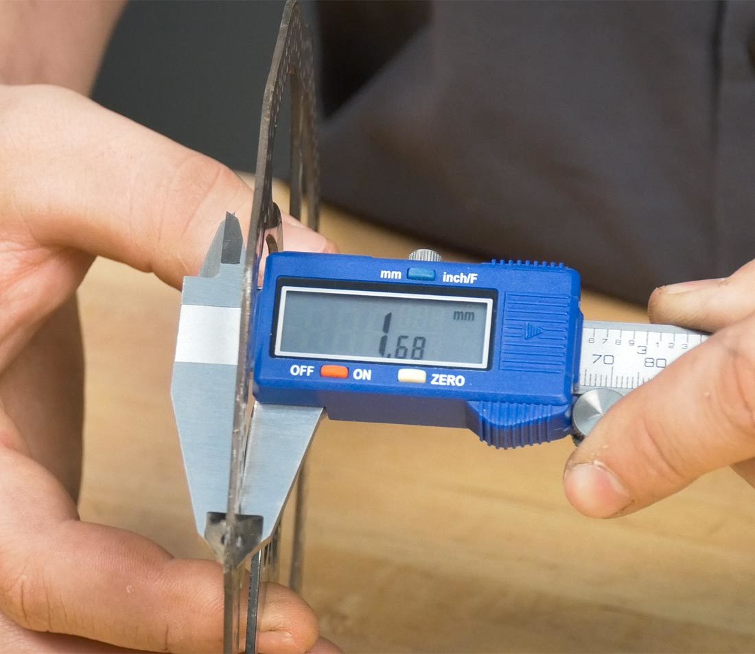
This measurement can be compared to an unused section of the rotor or to the manufacturer's recommendation
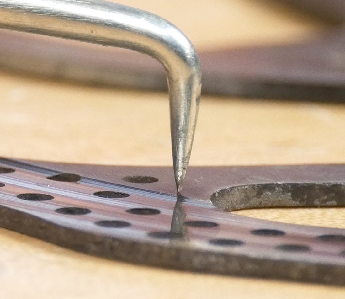
A utility pick makes it easier to feel a "step" on the edge of the rotor braking surface
2. Damaged / Bent Rotor
A bent rotor will be audible (rhythmic rub or noise as the wheel rotates) or visible (a lateral deviation as the rotor passes through the brake caliper). Re-bending is possible in some cases, but replacement is sometimes the best option. See our Disc Brake Rotor Truing article for more information.
3. Upgrade / Change Size
Perhaps you just want to upgrade to a better quality or larger diameter rotor.
There are 4 main sizes commonly used in the bike industry: 140, 160, 180 and 203mm. However, there are a few outliers that could apply to you, so be sure to double-check by measuring. Sometimes the size will be listed on the rotor. Otherwise, you will need a suitable measuring device for measuring the outer diameter.
In general, you will want to replace a rotor with one of the same size. If you are changing rotor sizes, you will likely need to make changes to your calipers or adapter as well. Check with the manufacturer for more information.
Rotor Selection Considerations
First and foremost, the rotor and hub should have the same interface. 6-bolt rotors are fastened with 6 bolts, while center-lock rotors are fastened with a lockring with either external notches or internal splines. It is possible to adapt a 6-bolt to a center-lock rotor, but it is not possible to adapt a center lock to 6-bolt. Scroll to the adapter section to learn more.
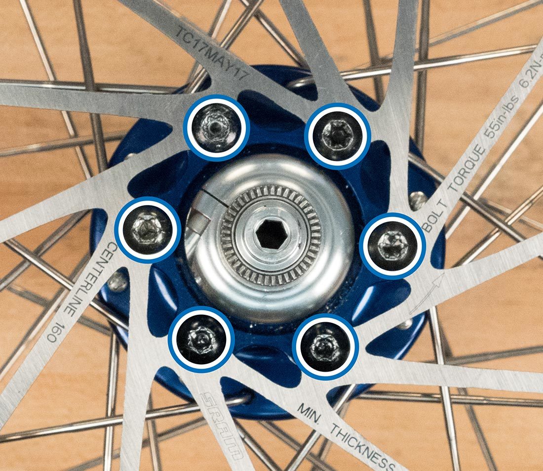
6-bolt rotor
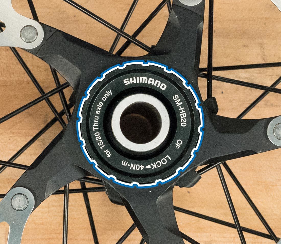
Center-lock rotor with external notch lockring
2
6-Bolt Rotors
Removal
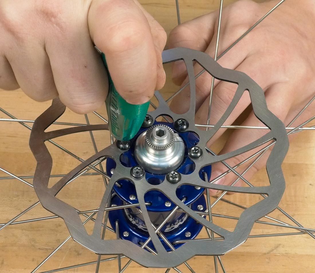
- Loosen and remove the rotor bolts using the appropriate wrench.
- After all the bolts are safely out, remove the rotor.
Installation
- If the rotor came with new bolts, check them for an aerobic threadlocker. If the bolts have no threadlocker, you can use thread prep such as Park Tool TLR-1 inside the hub rotor mounting holes. It only takes a little to be effective.
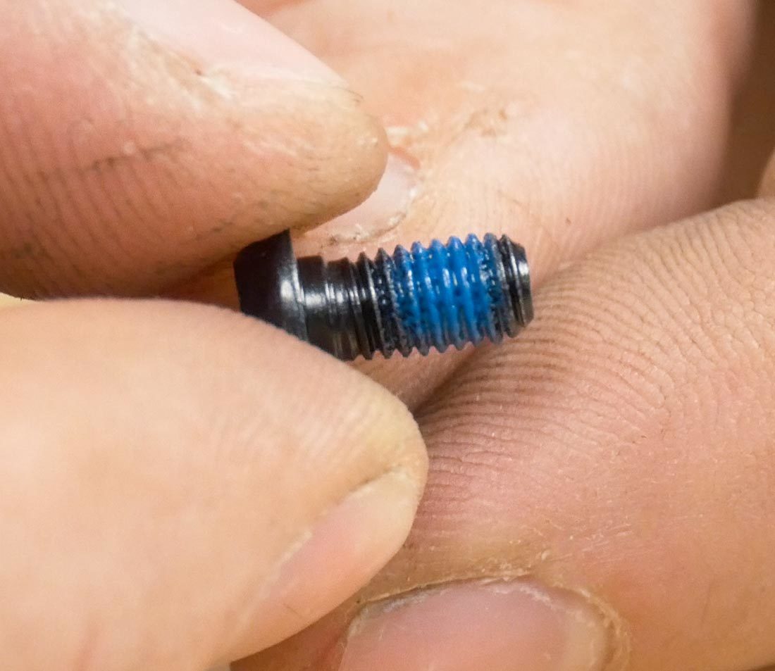
Rotor bolt with pre-applied threadlocker
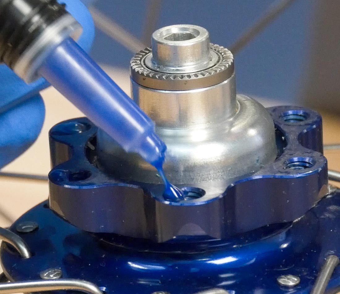
If needed, apply a single drop of threadlocker inside the mounting holes and wipe away the excess using a clean rag
IMPORTANT: Do not grease or oil the bolts. The oils can creep outward from the heat of braking and contaminate the rotor.
- Determine the correct rotor orientation. Most rotor designs feature an arrow, which should match the rotation of the wheel. Otherwise, orient the rotor so the side with writing is facing out.
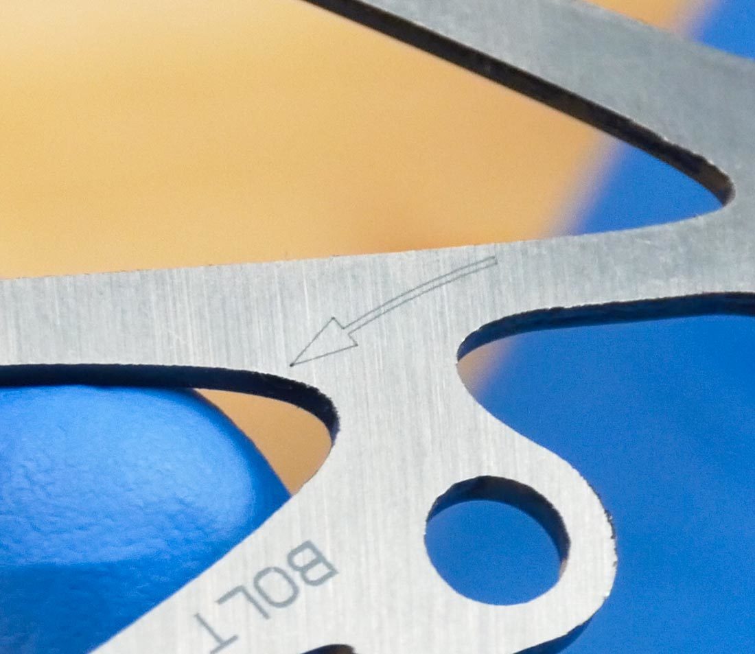
Any arrow on the disc should match the direction of wheel rotation
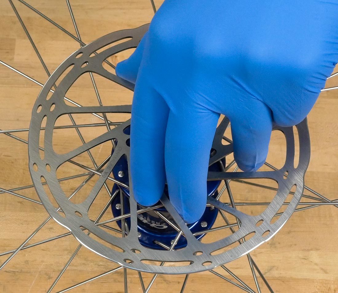
Nitrile gloves prevent contamination from dirty hands
- Place the rotor on the hub, handling the rotor from the inside edges. Line up the holes on the rotor with the mounting holes of the hub.
- Hand thread the rotor bolts, making sure to not cross thread them.
- Thread the bolts in so they are close to but not touching the rotor face.
- Clock the rotor in a clockwise direction to mate the front edge of the rotor against the bolts, then snug the bolts while holding the rotor in place. This is done to reduce any sudden shearing force that may happen if movement occurs during braking.

- Tighten the bolts in a star pattern, tightening every other bolt until they are all properly torqued. Refer to the animation below for reference.
- Typical torque for these bolts is about 4–6 Nm. If you're using a hand wrench, use perceived effort, which means applying about 11 pounds of effort to a wrench held 4″ from the bolt.
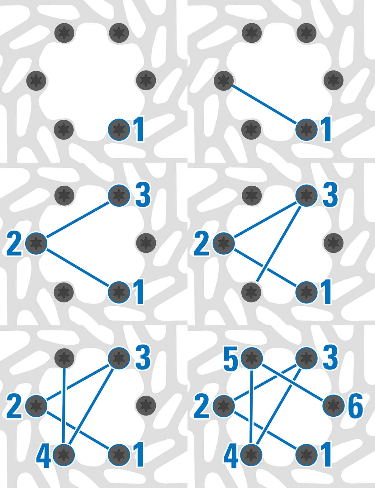
- Use a clean rag and isopropyl alcohol to wipe both sides of the rotor surfaces.
- Reinstall the wheel on the bike. Spin the wheel to verify that your caliper alignment is still good. sometimes rotors are just slightly different from each other, causing the calipers to need realignment. Refer to our Repair Help on disc brake caliper alignment for more information.
3
Center-Lock Rotors
Removal
- Start by determining what style of tool you need. Its fairly easy to identify the difference between lockring standards.
- If there are notches on the outside of the lockring you will need a BBT-9, BBT-69.2 or similar tool.
- If there are notches on the inside and no notches on the outside, you will need one of the FR-5.2 family of tools.

External-notched lockring

BBT-69.2 Lockring Tool
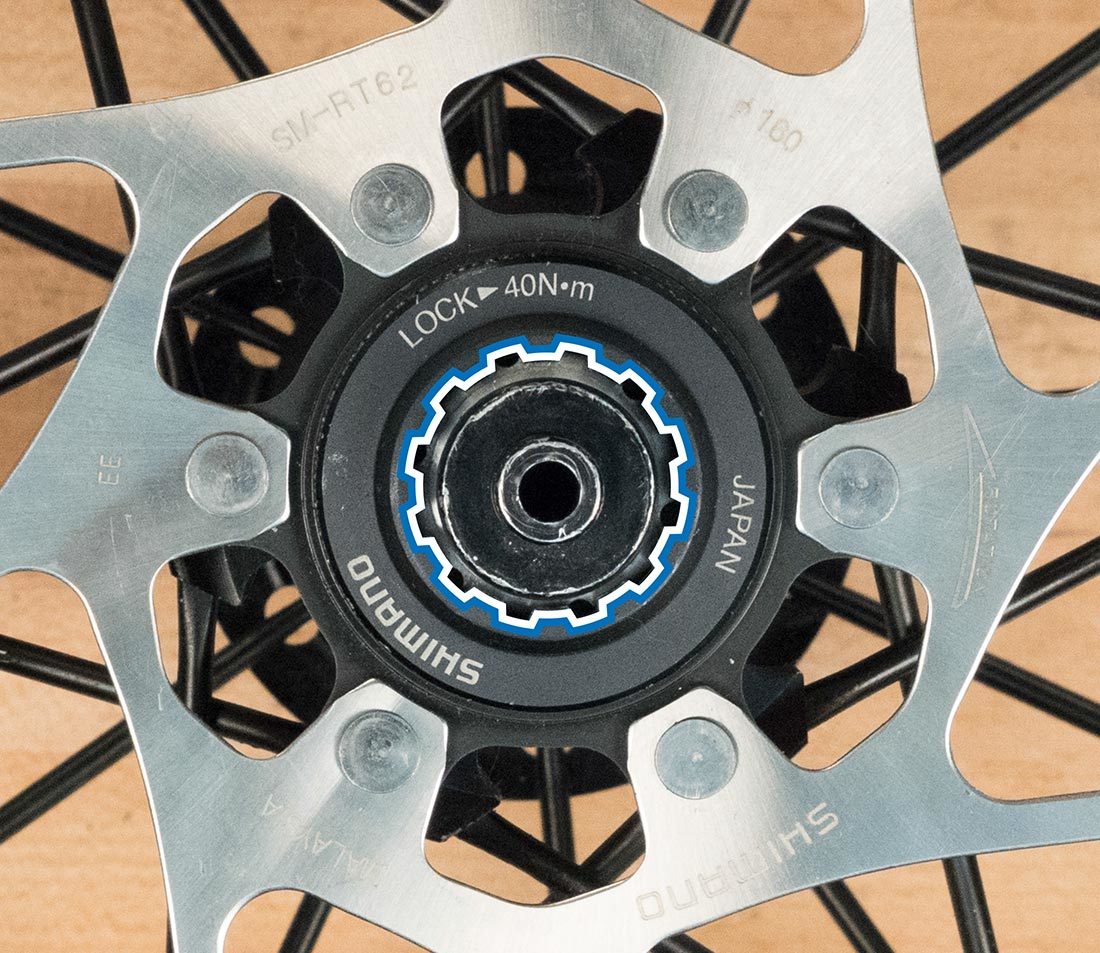
Lockring with internal splines
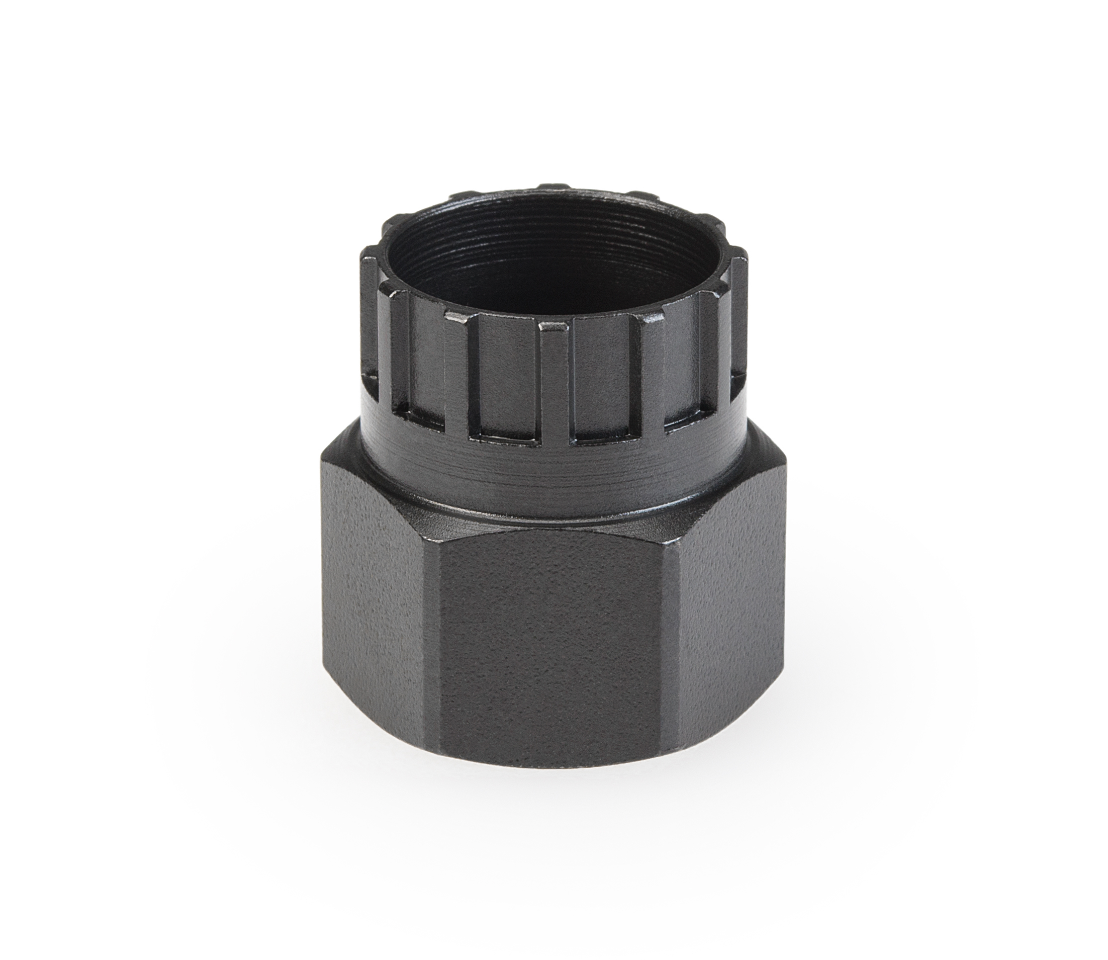
FR-5.2 Lockring Tool
- Engage the tool on the lockring. Loosen counter-clockwise and remove the ring.
- Pull the rotor from the hub.
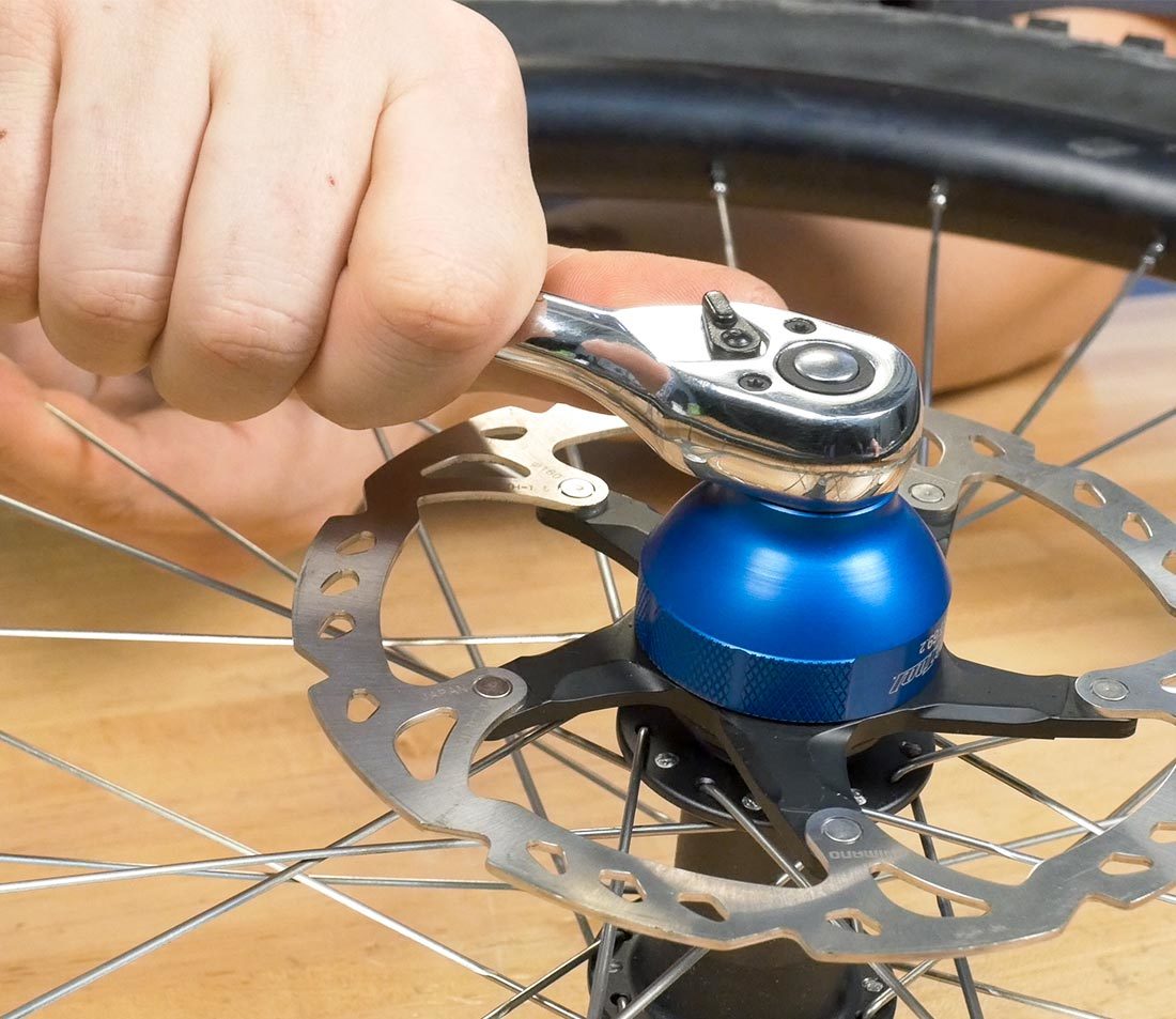
Installation
- Clean your work area. When installing the new rotor, it is important for the rotor braking surface to stay free of contaminants. Avoid touching it with your hands.
- Determine the correct rotor orientation. Most rotor designs feature an arrow, which should match the rotation of the wheel. Otherwise, orient the rotor so the side with writing is facing out.
- Slide the rotor into place and hand tighten the lockring.
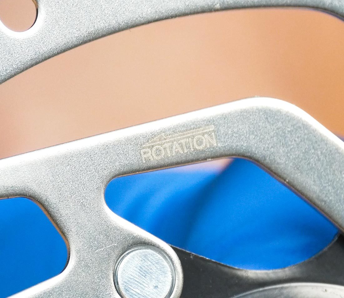
Any arrow on the disc should match the direction of wheel rotation
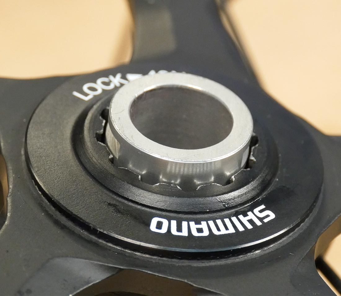
Internally splined lockrings may be incompatible with some hub axle sizes. A lockring tool cannot engage in this configuration. Solve this by using a lockring with external notches.
IMPORTANT: Grease is not necessary for center-lock rotors and may contaminate the rotor surface, so do not apply grease to any components.
- Torque the lockring to manufacturer's specifications. This example is 40 Nm — if you are using a hand wrench, that is about 44 pounds of effort holding the wrench 8″ from the lockring.
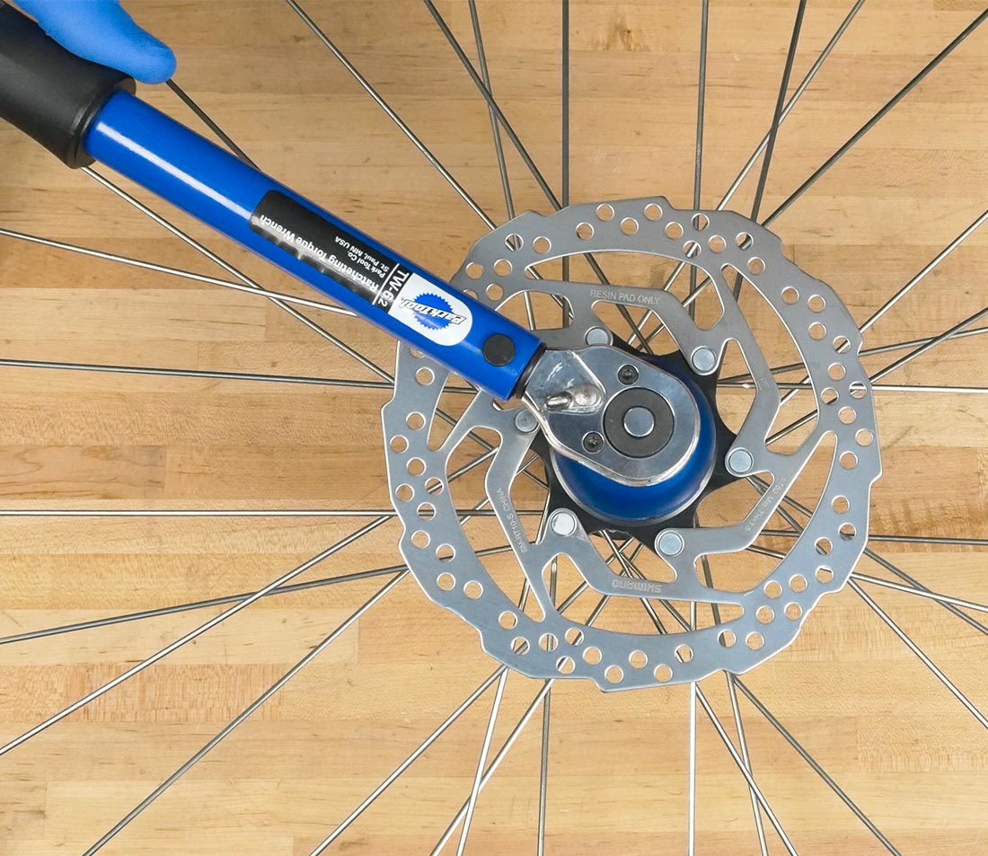
- Use a clean rag and isopropyl alcohol to wipe both sides of the rotor surfaces.
- Reinstall wheel on the bike. Spin the wheel to verify that your caliper alignment is still good. sometimes rotors are just slightly different from each other, causing the calipers to need realignment. Refer to our Disc Brake Caliper Alignment guides for Mechanical and Hydraulic systems.
4
Rotor Adapters
A 6-bolt rotor can be installed on a center-lock hub by using an adapter kit designed for this purpose. These kits vary slightly from design to design. Here are two examples:
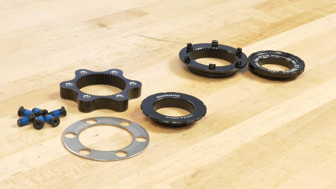
Example #1: Shimano
- Mate the adapter with the hub.
- Thread the bolts through the rotor into the adaptor.
- Clock the rotor and torque the bolts to the adapter in a star pattern, just as you would when installing onto a 6-bolt hub.
- Install any washers as applicable.
- Thread on and torque the lockring.
Example #2: DT Swiss
- Mate the adapter with the hub.
- Engage the rotor with the 6 fittings on the adapter.
- Thread on the lockring, clock the rotor & torque the lockring.
Neww Brake Tool That Has For Both Rotor Design
Source: https://www.parktool.com/blog/repair-help/disc-brake-rotor-removal-installation
Posted by: kimafor1996.blogspot.com

0 Response to "Neww Brake Tool That Has For Both Rotor Design"
Post a Comment